
How RS-485 Actually Works: A Practical Engineer's Guide
RS-485 is one of those things that gets used everywhere without many people ever really needing to think about what is happening electrically.
Connect A to A. Connect B to B. Daisy-chain the devices. Fit the termination resistor. Set the address. If it talks, move on.
That is fine until it stops talking.
Then you are standing in front of a panel with a meter, wondering why both conductors have voltage on them, why swapping A and B sometimes fixes the problem, why one badly wired network works perfectly and another does not, or why adding a 120 Ω resistor suddenly brings everything back to life.
The first thing worth getting straight is this:
RS-485 is not a communications protocol.
It is an electrical standard. It defines how signals are transmitted and received over a balanced pair.
Protocols such as Modbus RTU and BACnet MS/TP can run over RS-485, as can countless proprietary protocols used in fire alarm systems, smoke control, access control, BMS equipment, drives and industrial controls.
RS-485 gets the electrical signal from one device to another.
The protocol decides what that signal means.
Start with A and B
At its simplest, an RS-485 network uses two conductors, normally called A and B.
A transmitter does not simply put a voltage onto one conductor relative to earth. It creates a voltage difference between the two conductors.
For example:
A = 3.5 V
B = 1.5 V
The differential voltage is:
Vdiff = VA - VB
Vdiff = +2 V
The opposite state might look like this:
A = 1.5 V
B = 3.5 V
Giving:
Vdiff = -2 V
The important part is not the absolute voltage on A or B.
It is the difference between them.
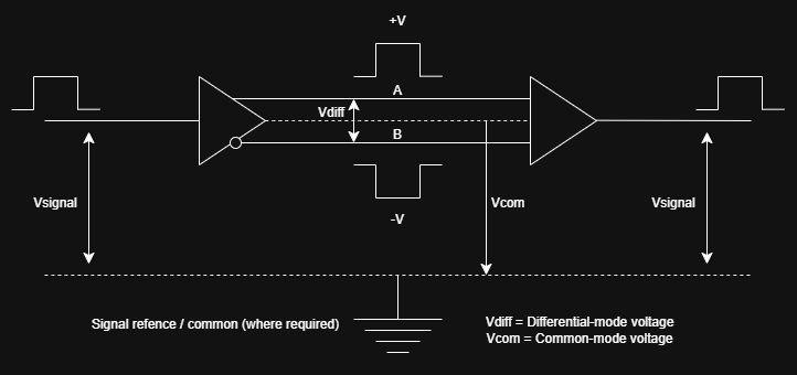
The receiver is mainly interested in the voltage difference between A and B, while both conductors still have to remain within the transceiver's permitted common-mode voltage range.*
The diagram shows two different quantities:
Vdiff is the differential voltage between A and B.
Vcom is the common-mode voltage of the pair relative to the local signal reference.
Both matter, but for different reasons.
Why differential signalling works so well
The big advantage of differential signalling is noise rejection.
Say some electrical interference adds roughly 1 V to both conductors.
Instead of:
A = 3.5 V
B = 1.5 V
you might now see:
A = 4.5 V
B = 2.5 V
But:
4.5 - 2.5 = 2 V
The differential voltage is still the same.
That interference has affected both conductors in roughly the same way, so it is common-mode noise.
A differential receiver is interested mainly in the difference between A and B, so a lot of that noise can be ignored.
That is one of the reasons RS-485 works so well around things like:
- motors
- contactors
- VSDs
- switchgear
- relays
- long cable runs
It is not immune to interference. It is just very good at rejecting noise that appears on both conductors together.
Why the cable is twisted
The pair is twisted so A and B experience the surrounding electrical environment as similarly as possible.
If one conductor ran closer to a source of interference for the whole cable route, it could pick up more noise than the other.
Twisting the pair keeps swapping their physical positions.
Over the length of the cable, the interference tends to be shared more evenly between them.
That is exactly what you want with differential signalling.
The more similar the unwanted noise is on both conductors, the easier it is for the receiver to reject it.
What actually drives the pair?
Inside an RS-485 transceiver is a differential driver.
For one state, it creates a voltage difference across A and B in one direction.
For the opposite state, it reverses that difference.
The driver also has to maintain that differential voltage while connected to the electrical load presented by the rest of the network.
This is where the old "32 devices" rule gets oversimplified.
RS-485 loading is actually defined in terms of unit loads.
A traditional receiver may represent one full unit load, with the driver expected to support up to 32 unit loads.
Modern receivers often present much less load. You will see devices rated as:
- 1/2 unit load
- 1/4 unit load
- 1/8 unit load
So a network can have more than 32 physical devices on it, provided the total loading stays within the driver's limits.
The real question is not simply:
How many devices are connected?
It is:
How much electrical load are those devices putting on the bus?
How can several devices share the same pair?
On a typical two-wire RS-485 network, every device is connected to the same pair.
That does not mean every device drives the pair at once.
When a device is not transmitting, its driver goes into a high-impedance state.
In practical terms, it stops actively driving the line, but it can still listen.
That leaves another device free to take control of the bus.
A simple way to picture it is a group of people sharing one microphone.
Everyone can hear what is being said.
Normally, only one person speaks at a time.
Who gets to speak, when they speak and what their message means are all decided by the protocol running over RS-485.
RS-485 itself does not define:
- device addresses
- commands
- registers
- checksums
- responses
- master and slave behaviour
It only handles the electrical side.
Half-duplex and full-duplex
Most RS-485 networks used in building services are two-wire half-duplex systems.
The same pair is used in both directions.
That means either side can transmit, but not normally at the same time.
Four-wire RS-485 uses separate pairs for transmit and receive:
TX+ / TX-
RX+ / RX-
That allows simultaneous transmission and reception.
It exists, but two-wire half-duplex is much more common in multidrop control systems.
Why RS-485 is normally daisy-chained
One of the most common RS-485 rules is:
Do not star-wire it.
The reason becomes clearer once you stop thinking of the cable as a perfect connection.
At fast enough signal edges and over long enough cable runs, the cable behaves as a transmission line.
A voltage change travels along the cable as an electromagnetic wave.
When that wave reaches a discontinuity, such as the end of a cable or a long branch, some of the energy can reflect back down the line.
A receiver may then see the original transition followed by one or more delayed reflections.
At low speeds and short distances, that may not matter at all.
At higher speeds or over longer runs, those reflections can distort the waveform enough to cause communication errors.
That is why RS-485 is normally installed as one continuous trunk with short stubs to each device.
A star introduces several branches and several places for reflections to occur.
What the 120 Ω resistor actually does
The famous 120 Ω termination resistor is not magic.
A typical twisted-pair cable used for RS-485 has a characteristic impedance somewhere around 120 Ω.
When a signal reaches the end of an unterminated cable, the sudden change in impedance can cause part of that signal to reflect.
Putting a resistor across A and B at the end of the line, with a resistance close to the cable's characteristic impedance, helps absorb that energy instead.
That is why termination resistors normally belong at the physical ends of the bus.
Not at every device.
If you fitted 120 Ω across every node, you would quickly load the driver far too heavily.
With a 120 Ω resistor at each end of the bus, the driver already sees roughly:
120 Ω || 120 Ω = 60 Ω
before receiver loading is taken into account.
Does every RS-485 network need termination?
No.
A short network running at a low data rate can often work perfectly well without it.
The reflections may settle quickly enough that they never interfere with the point at which the receiver decides whether the next bit is high or low.
As the cable gets longer and the signalling speed increases, correct termination becomes more important.
This is why you sometimes find terrible RS-485 wiring that has worked for years.
The rules are not wrong.
That particular network just has enough margin to get away with it.
There is a big difference between:
It works.
and:
It is correctly engineered.
What are bias resistors for?
Another problem appears when nobody is transmitting.
If every transmitter is in its high-impedance state, there may be no active driver holding the pair in a clear differential state.
Without some sort of fail-safe arrangement, noise around that idle condition could potentially be interpreted as data.
Bias resistors are used to establish a known idle condition.
A typical arrangement gently pulls one conductor towards the positive supply and the other towards the local reference through suitable resistors.
Modern RS-485 receivers often include internal fail-safe circuitry, so external biasing is not always required.
Where external biasing is used, it needs to be designed as part of the network.
Randomly adding pull-up and pull-down resistors to every device is not the same thing.
If RS-485 is differential, why does common-mode voltage matter?
This is where RS-485 explanations often get oversimplified.
You will sometimes hear:
RS-485 does not need a ground because it is differential.
That is only partly useful.
The receiver measures the difference between A and B, but its input circuitry still has limits on how far those conductors can move relative to its own local reference.
Look back at the diagram.
Vdiff is the difference between A and B.
Vcom tells us where the pair is sitting relative to the local signal reference.
You can have a perfectly valid differential voltage while the common-mode voltage is outside the receiver's permitted range.
For example, two devices may be powered from separate supplies.
If their local reference potentials differ significantly, both A and B can shift relative to the receiving device.
The difference between A and B may still be correct, but the transceiver inputs may now be outside the range they were designed to handle.
This matters more when equipment is:
- powered from separate supplies
- located a long way apart
- installed across different electrical environments
- subject to earth potential differences
- exposed to heavy electrical noise
Depending on the equipment and the installation, a signal reference conductor may be required.
In more demanding applications, galvanically isolated RS-485 interfaces may be used instead.
So the useful answer is not:
RS-485 needs a ground.
or:
RS-485 does not need a ground.
It is:
The bus has to remain within the common-mode limits of the transceivers.
Why are A and B sometimes backwards?
Because the naming convention is inconsistent.
Different manufacturers have historically used A/B and +/- terminology in different ways.
Documentation is not always consistent either.
So this:
A → A
B → B
is not an absolute guarantee that two devices will communicate.
The correct approach is to check the manufacturer's definition of the terminals.
If two devices only communicate when their labelled A and B conductors are crossed, nothing strange is happening electrically.
The manufacturers may simply be using opposite naming conventions.
Why a multimeter can be misleading
This is particularly relevant when fault-finding in the field.
You might measure:
A = 2.8 V
B = 2.1 V
and think:
There is voltage there, so the RS-485 must be fine.
Unfortunately, that does not tell you very much.
A multimeter is showing an averaged measurement of a rapidly changing digital signal.
It does not show you:
- waveform shape
- ringing
- reflections
- individual bit levels
- timing
- collisions
- noise spikes
- baud rate
- framing errors
- corrupted data
A network can show completely believable DC voltages while being unable to communicate reliably.
An oscilloscope tells you far more about the physical layer.
A protocol analyser tells you what the devices are actually transmitting.
Sometimes you need both.
RS-485 and Modbus are not the same thing
These terms get used interchangeably far too often.
They are not the same thing.
RS-485 describes how the electrical signal is transported.
Modbus RTU describes what the data means.
Modbus RTU can run over RS-485, but RS-485 itself has no concept of:
- Modbus addresses
- function codes
- registers
- CRCs
- device commands
A manufacturer can just as easily run a proprietary protocol over exactly the same RS-485 physical layer.
That is extremely common in fire alarm, smoke control, access control and other building systems.
So what is RS-485, really?
Strip it back and the idea is fairly simple.
Two conductors carry information as a difference in voltage.
The pair is twisted so external interference tends to affect both conductors in a similar way.
Several devices can share the same bus because transmitters stop driving the pair when they are not speaking.
Termination controls reflections.
Biasing can establish a known idle state.
The common-mode voltage has to remain within the limits of the transceivers.
Then another protocol decides what all of those bits actually mean.
That combination of simplicity, low cost and electrical robustness is why RS-485 is still everywhere.
You will find it in fire alarm systems, smoke control equipment, access control, BMS networks, drives, PLCs, meters and industrial controls.
Once you understand what Vdiff and Vcom actually represent, and what is physically happening on A and B, fault-finding RS-485 becomes a lot less mysterious.