 Fire Secure UK
Monitored Inputs - Sprinkler Valve Sets
Overview
Sprinkler systems commonly provide two separate status signals that must be monitored by the fire alarm system:
- A flow switch, which operates when water flows through the sprinkler system and generates a fire alarm condition.
- An isolation valve tamper switch, which operates when a monitored valve is closed or moved from its normal position and generates a fault or supervisory condition.
Where input capacity is limited, or where the fire alarm system is designed to interpret multiple circuit states from a single monitored input, both devices can often be connected to the same supervised circuit using resistor monitoring.
By measuring the resistance present on the circuit, the control panel or input module can distinguish between:
Normal operation Sprinkler flow alarm Valve tamper condition Open circuit faults Short circuit faults
Several resistor supervision methods are used throughout the industry. The most common modern approach is parallel resistor monitoring, where operation of the flow switch introduces a second resistor in parallel with the End of Line (EOL) resistor. However, some systems utilise series resistor monitoring, where resistor values are switched or added in series to produce different circuit states.
The diagrams on this page demonstrate the monitoring principles commonly used when interfacing sprinkler flow switches and isolation valve tamper switches with a single monitored input. As resistor values and resistance thresholds vary considerably between manufacturers, the diagrams intentionally focus on circuit topology rather than specific resistor values.
Why Use Monitored Inputs?
Monitored inputs provide significantly greater fault tolerance than conventional contact circuits.
A simple contact circuit can typically only determine whether a contact is open or closed. If a cable becomes disconnected or damaged, the control equipment may be unable to determine whether a fault has occurred or whether the monitored device has simply changed state.
By monitoring circuit resistance, the control equipment can detect:
- Cable breaks
- Loose connections
- Short circuits
- Device operation
- Tamper conditions
This improves system reliability and helps ensure faults are identified before they prevent correct operation.
Common Applications
Monitored inputs are commonly used for:
Fire Alarm Systems
- Sprinkler flow switches
- Isolation valve tamper switches
- Pressure switches
- Suppression system interfaces
- Generator status monitoring
- Fire pump monitoring
- Ancillary fire system interfaces
Smoke Control Systems
- Fan status monitoring
- Damper position monitoring
- Firefighter control interfaces
- External fault indications
Security Systems
- Door contacts
- Intruder alarm zones
- Equipment tamper monitoring
Building Management Systems
- Equipment status monitoring
- Alarm inputs
- Plant fault monitoring
Sprinkler Flow and Valve Tamper Monitoring
One of the most common monitored input applications is the connection of a sprinkler flow switch and isolation valve tamper switch to a single supervised input.
In this arrangement:
- The flow switch generates an alarm condition.
- The valve tamper switch generates a fault or supervisory condition.
- A single monitored input distinguishes between normal, alarm and fault states.
Several monitoring methods are commonly encountered.
Parallel Resistor Monitoring
Parallel resistor monitoring is one of the most common approaches encountered on modern monitored inputs.
Under normal conditions the End of Line (EOL) resistor remains permanently connected to the circuit.
When the flow switch operates, an additional resistor is introduced in parallel with the EOL resistor. This changes the total resistance seen by the monitored input and causes the circuit to enter the alarm state.
If the tamper switch operates, the circuit is interrupted, resulting in an open circuit fault condition.
Diagram
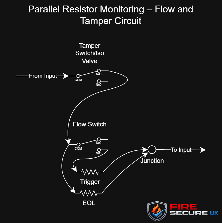
Circuit States
| Condition | Description |
|---|---|
| Normal | EOL resistor present |
| Alarm | Trigger resistor connected in parallel with EOL resistor |
| Fault | Open circuit |
| Short Circuit | Resistance below configured threshold |
Advantages
- Simple wiring arrangement
- Commonly supported by modern monitored inputs
- Clear distinction between alarm and fault conditions
- Suitable for sprinkler monitoring applications
Series Resistor Monitoring
Series resistor monitoring achieves the same functional outcome using a different resistor arrangement.
Instead of introducing a resistor in parallel, the circuit resistance changes through the addition, removal or switching of resistors in series with the monitored circuit.
Although less commonly encountered than the parallel method, it remains present on some systems and manufacturer-specific implementations.
Diagram
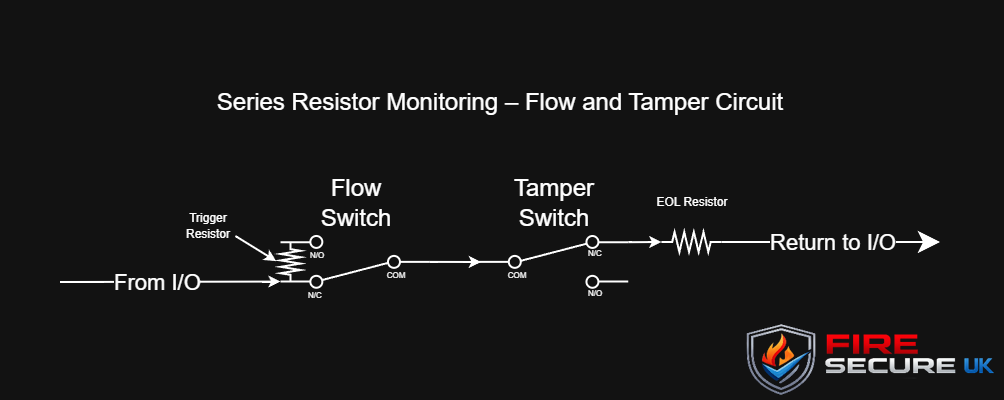
Circuit States
| Condition | Description |
|---|---|
| Normal | Expected resistance present |
| Alarm | Resistance changes to alarm value |
| Fault | Open circuit |
| Short Circuit | Resistance below configured threshold |
Advantages
- Simple implementation on some monitored inputs
- Can provide reliable multi-state monitoring
- Supported by various legacy and manufacturer-specific systems
Resistor Values
There is no universal resistor value for monitored inputs.
Manufacturers use different resistor values and resistance thresholds depending on:
- Control panel design
- Input module design
- Protocol requirements
- Number of supervised states required
Examples may include:
- End of Line (EOL) resistors
- Trigger resistors
- Alarm resistors
- Fault resistors
Always consult the relevant manufacturer documentation before commissioning or fault-finding a monitored input circuit.
Fault Finding
When fault-finding monitored inputs it is important to understand the monitoring philosophy used by the system.
A common mistake is assuming that all systems use the same resistor arrangement or resistor values.
Before investigating a fault:
- Identify the monitored input type.
- Obtain the relevant manufacturer documentation.
- Confirm expected resistance values.
- Measure the resistance at the control equipment.
- Verify operation of all field devices.
- Check for open circuits, shorts and poor connections.
Understanding how the control equipment interprets resistance changes can significantly reduce fault-finding time.
Summary
Monitored inputs allow multiple circuit conditions to be identified using a single pair of conductors through resistance supervision.
For sprinkler monitoring applications, both parallel and series resistor methods may be encountered, allowing a single monitored input to distinguish between normal, alarm and fault conditions.
Although resistor values vary between manufacturers, the principles shown on this page remain applicable across many fire alarm, sprinkler, smoke control and security systems.